Intro
My home assistant set-up is one of my first DIY projects that I picked up when I moved to Utrecht. It is also the one that keeps adding tasks/improvements to my hobby-backlog, so it basically goes on forever. Its current setup deserves a bit of love in the form of a blog post as well, but for today I just want to focus on one of my latest addition: Motorized sliders😍.
DI-why?
The other day I was talking with my friend Berend, when He mentioned something about sliders. You know, those things they use in old midi panels.
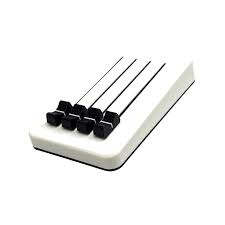
These are pretty nifty, and gave me the idea to integrate in my smart home setup. That way, I can control my lights with something that almost resembles a physical switch, but then without it being reliable😅. Yeah, my relationship is definitly love/hate, but once you’re in, there is no way you would throw away all that hard work and tears.
Anyway, there was one big problem with sliders, they don’t update state whenever something is changed outside of the slider. Let’s say that I use the slider to dim my light to 50% brightness, and then change it from my home assistant UI or some other integration (I use adaptive lighting to control my brightness/color temperature). This would result in the slider being in a stale state, which is unacceptable (for me).
Fortunately, there is a concept of motorized sliders! With these, I can make manual adjustments, while having the ability to update its position from home assistant. Perfect!
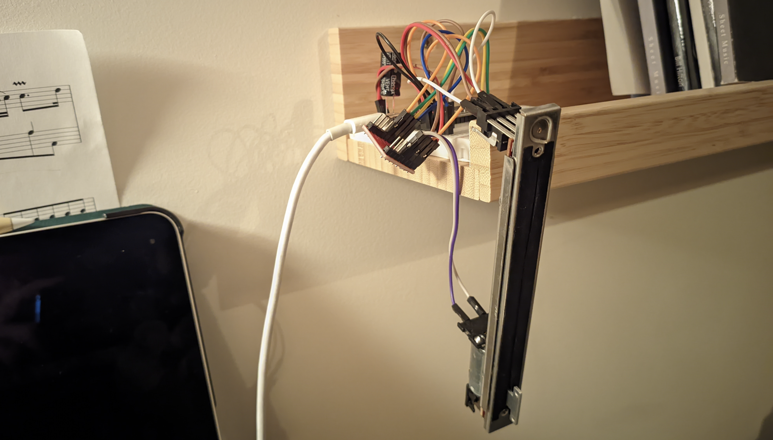
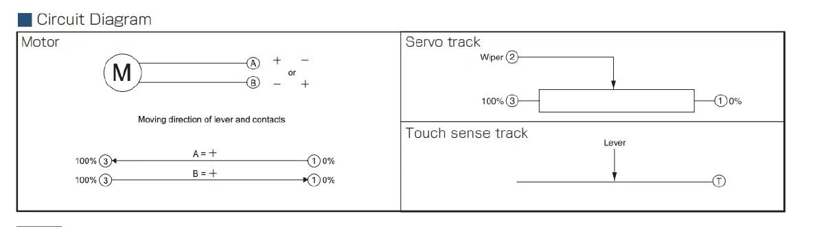
I ordered my sliders from the very reputable Aliexpress. Here is the datasheet, in case you are interested: Rsa0n11m9a0j.

The working principles are quite simple, and the pins are shown in the snippet from the datasheet below. There is a motor that can be reversed in direction by switching the poles (I used an TB6612 breakout board for that). The other part is just a simple potentiometer. You can read the position of the slider, by measuring the voltage over pin 2-1, when 3.3v is applied to pin 3. When the slider is half way, you’ll have a voltage divider with (effectively) two equivalent resistors, resulting in a voltage of approx 1.65v. The final pin is a touch sense track. First, I figured I won’t need that, but in the end I started using it anyway, as it makes the control software a lot simplier.
- Building a external component, which I will then include in my ESPHome config;
- Trying to get all the logic in my ESPHome config
I found the documentation of the external component creation a bit confusing at first, and since my logic is going to be quite simple, I figured I’d rather implement the logic in the config file. I still think both are feasible options, but as you might see later, you still need to configure quite a bit of pins in the ESPhome config, even if you decide to go for a custom component.
To detect if the slider is touched, I used one of the touch GPIO pins that the ESP32 supports. After a bit of testing with the threshold I decided on the following config:
|
|
To readout the slider, I use the ADC of the ESP32. There are a couple of considerations:
- We want to readout the value quite often. When the slider is moving, we want to know exactly when to stop. If it takes to long to get a new reading, you get an “overshoot” and possibly oscillating behaviour. I settled for a reading every millisecond
- We want to report the ADC reading to Home Assistant, but it is not desirable to do this 1000 times per second.
- the readings of our ADC might vary, but if we use sampling, we possibly slow down our control loop. We could instead use a seperate reading with a
sliding_window_moving_average, to consolidate the readings into a more accurate one. - In Home Assistant, we only want to update the slider postion, when it has changed.
All in all, I came up with the following config:
|
|
Next we need to set the pins of the H-bridge, so that we can control the motor speed an direction. It uses PWM to do this. I set the frequency to a value that should not be audible to human beings. I apologize to all the dogs that want to do this project themselves.
|
|
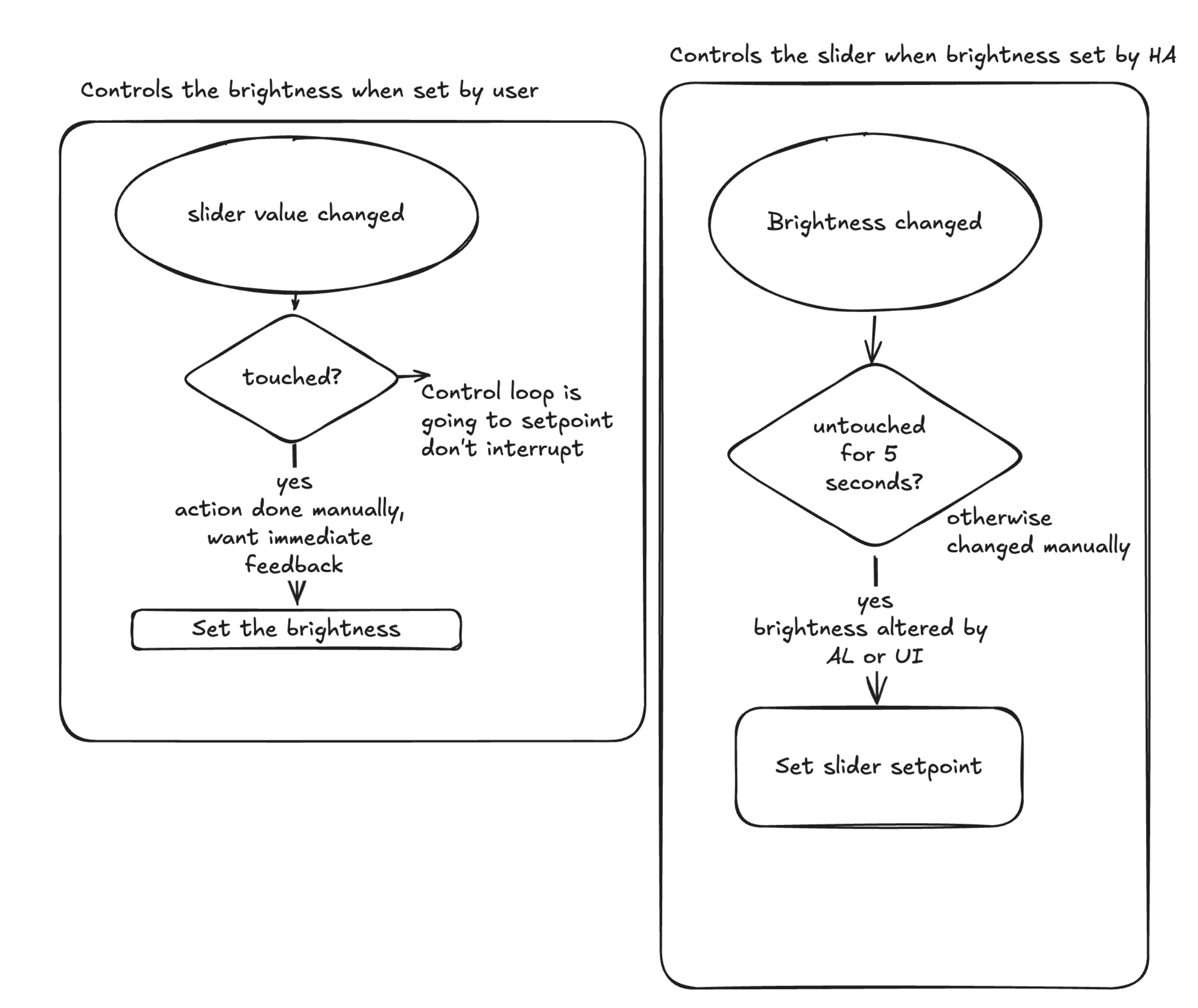
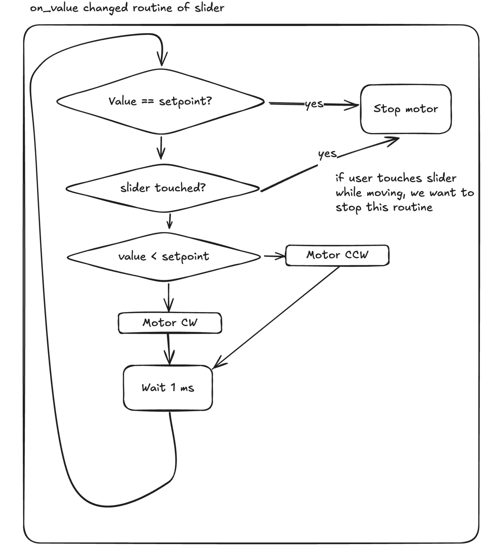
At last, I made a numeric slider component in ESPHome. This component can be set to a value 0-100 from home assistant. I also added a callback, so that the control loop is executed whenever the value is set. This code is pretty awful to read. I am not a huge fan of “programming” in yaml, but this was way easier that writing a custom component. Fortunately for you, I made a simple flowchart to show the logic:
 {style=“background-color:white; padding: 10px; border-radius: 5px;”}
The code (don’t show my boss):
|
|
This is pretty much it. After programming the device, it shows up in Home Assistant as we expect:
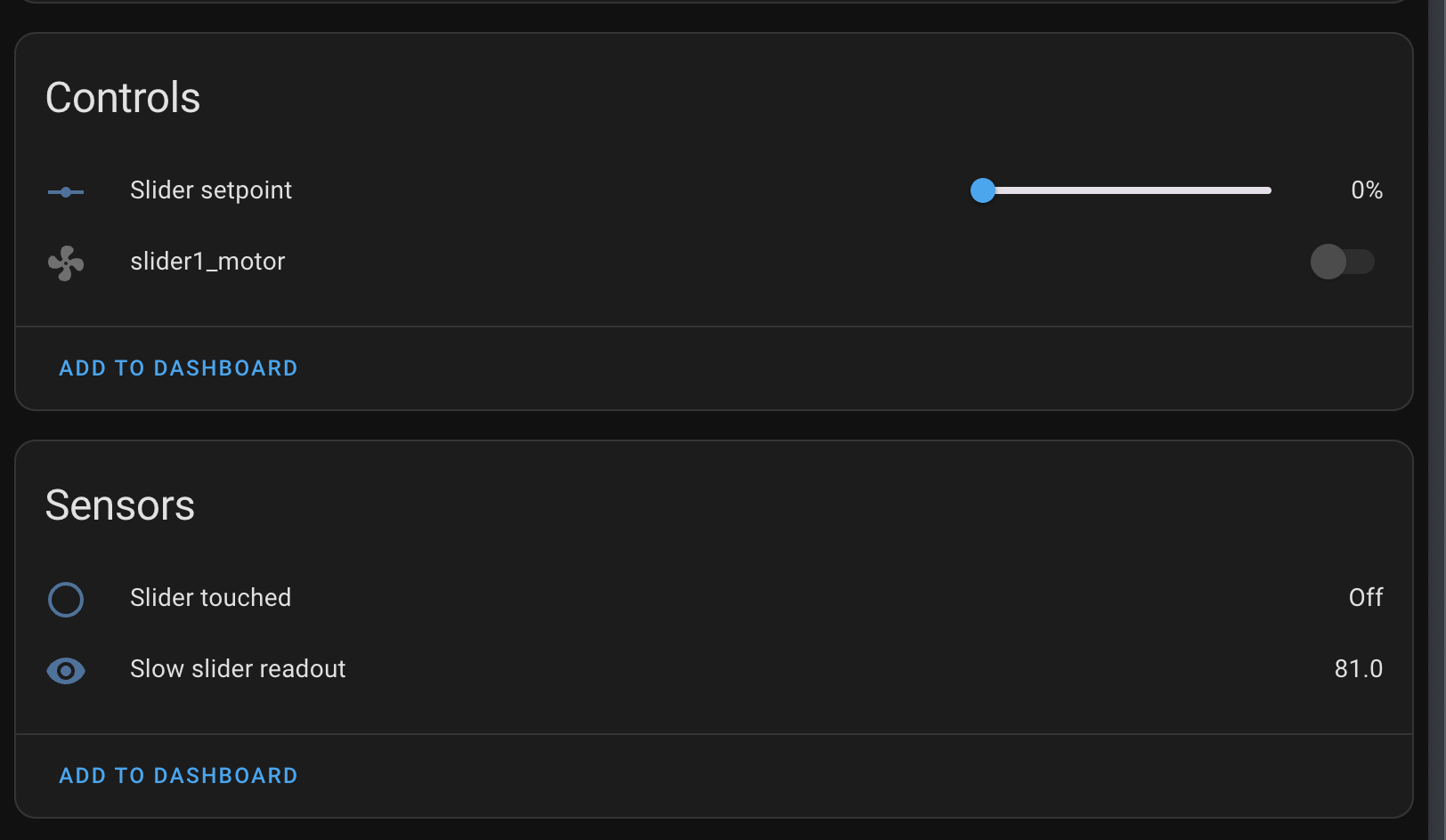
For some reason, we also have an entry slider1_motor. This one is from a previous config prior to writing this post, but somehow it still shows up. I don’t really mind. For creating an automation, I went with the following strategy:
In Home Assistant, you work with triggers (round boxes), conditions (diamond) and actions (square). The logic we want to incorporate has the following requirements:
- Whenever we change the slider by hand, we want no interruption by the motor
- Whenever we change the slider by hand, we want direct feedback (the lights should change brightness)
- Whenever Home Assistant changes the brightness, it should be reflected on the state of the slider.
Results
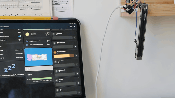
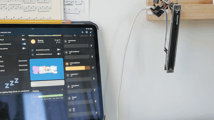
We’re done with the hardware and software, let’s look at the results!
Here we adjust the shifter manually, and you can see that as a result, the brightness in Home Assistant is adjusted.
Here we adjust the brightness in home assistant, and you see that the shifter is adjusted.
I will admit that I am not yet 100% satisfied with the results, but it works good enough for now! Point for improvement are:
- Overriding adaptive lighting when the light turns on initially (it automatically jumps to 79% in the video, this should not happen with manual override)
- The speed in which it responds. I am afraid this is difficult, the control algorithm already takes place on the ESP32, it’s just not as smooth as control by wire.
Overall it was a very nice little project where I learned a thing or two about ESPHome. Also, I now have a piano light with mediocre manual control. 😁